By doing so, they can thoroughly analyze and test each component or subsystem, increasing the chances of identifying and resolving any issues effectively.

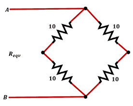
Since the branches are connected in parallel, each is exposed to 100 V. Due to the same resistances in each resistor, the two series resistors will only reduce the applied voltage by 50%.
Threads are made in a workpiece using taps. The three primary tap kinds are the bottoming tap, plus tap, and taper tap, as depicted in the image below. The number of threads in the chamfer region, as depicted, is the primary distinction between these varieties. The taper tap is typically used at the start of the threading process and has the fewest teeth. The plug tap is used to fix a threaded hole and has more teeth than the taper tap. While the bottoming tap, which is typically used to tap the hole's bottom, has a fairly even distribution of teeth along its length. The final tap to be utilized in the tapping procedure is the bottoming tap. Since the chamfered edge of a taper tap has the fewest teeth,
In serial communication, baud rate refers to the number of data bits sent and/or received each second. 110, 300, 600, 1200, 2400, 4800, 9600, 14400, 19200, 38400, 57600, 115200, 128000, and 256000 bits per second are among the common baud rates.
Voltmeters are always connected in parallel to the nodes in electrical circuits where it is necessary to measure the potential. To measure the desired current in the branches, ammeters are always connected in series.
Total harmonic distortion (THD) can be brought on by non-linear loads, such as power electronic devices (converters, inverters, etc.). These devices produce harmonic currents and voltages by drawing non-sinusoidal current from a sinusoidal voltage source, which distorts the wave shape.
The bare minimum fuse rating needs to be greater than the system's typical operating current. The total current in the system, while all three appliances are operating, is equal to the sum of the three since an electrical system is connected in parallel.
Each appliance's current usage is determined by:
I = P/V
Where:
P = Power [Watt]
V = Voltage [Volt]
Therefore, appliance A consumes 550/110 = 5A
Appliance B consumes 770/110 = 7A
Appliance C consumes 330/110 = 3A
The total current in the system is 5 + 7 + 3 = 15A
In order to withstand normal working conditions, the minimal fuse amperage rating must be greater than 15A, thus 20A.
The transformer receives an AC input voltage, and the rectified output is also displayed. Rectification, as can be seen, is the process of flipping the input's negative cycle to its positive side. 100 is the right answer since a full-output wave's frequency is twice as high as its input frequency.
The following equation describes the relationship between the load (L), the pulling force (F), and the number of pulleys (N): L = NF = 4 * 500, which results in L =4 * 500 = 2000lb.
The electric motor is started and stopped by this PLC program, which also establishes trip conditions in the event of excessive vibration, overcurrent (overload), and high winding temperatures. The vibration contact, X2, is closed in the absence of vibrations and open in the presence of vibrations. Given that it is a true statement
A motor's spinning will be reversed if two of its three terminals are switched. The way a forward-reverse starter operates is just like that.
Hexadecimal numbers have a base of 16 digits, ranging from 0 to 9, followed by letters A through F. Any number preceded by "0x" is a hexadecimal number, while any number followed by "b" is a binary number. Four binary bits are used to represent each hexadecimal number. The resultant binary of the provided integer will have 8 binary bits because there are 2 hexadecimal numbers.
Electricity is used to erase flash memory and EEPROMs. Higher voltages are used to program or delete flash memories, which erases the memory. These voltages are typically higher than the PC voltage, falling in the 5 to 15 V range.
Higher current switches/relays cause sparks to form on the contact terminals. Electromechanical relays should not be used because sparks are generated during the mechanical contact-making process.
Induction motors have two different ways of defining speed. Synchronous speed is the rate at which the magnetic field is changing. While the rotor's speed is referred to as the asynchronous speed. Slip is the term for the difference between these two.
If OL1 opens from rung 1, it is assumed that conveyor motor M1 will stop, and usually open (NO) contact M1 will change to 0. Since conveyor motors 2 and 3 are not reliant on M1 NO as can be seen in rungs 2 and 3, they will continue to operate.